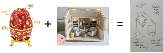
As outlined in the Week 01 assignment, I am planning to create a musical box that features a photo-screening function using a projector. This is a project I have been envisioning for a long time, even before I joined the Singapore Polytechnic FabLab team. Personally, I have always loved both music and drawing, which inspired me to design a personalized music box that can display my artwork from my childhood. However, as I began learning the theories and skills required to bring this idea to life, I realized it would be more challenging than I initially thought, mainly due to: 1. My limited background in Electrical and Electronic Engineering, which makes it difficult for me to understand and work with the necessary components and wiring. 2. My uncertainty about which components would be most suitable for my design. Nonetheless, I am grateful for the opportunity to be part of the FabLab team, where I can develop the skills and knowledge needed to "Make (Almost) Anything".
Week 02 - Bill of Material (BOM) + Parametric Design
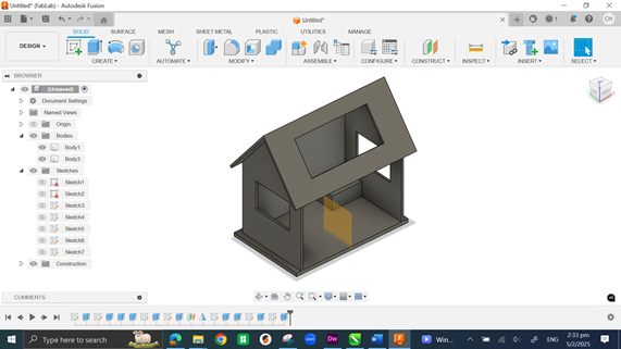
This week, I began considering the possible components needed to help realize my dream product: o Self-made musical box components. o A mini projector capable of flashing montages or photo slides, along with an accompanying screen. o A 3D-printed or laser-cut enclosure. o Various electronic components to facilitate communication between the musical mechanism and the projector system. After reviewing the list, I realized it would be very challenging to fit all the parts into a tiny egg-shaped shell as initially planned. As a result, I decided to redesign the enclosure into a DIY house-shaped box, providing more internal space to accommodate all the components. To support this, I started familiarizing myself with Fusion 360 for 3D design. I created a simple house structure using parametric design concepts — without setting fixed dimensions yet — which will make future modifications much easier and faster.
Week 03 - Suggestion for Final Project from Colleagues
One afternoon, while having lunch with my colleagues (all of whom have completed the Fab Academy course), they asked about the final projects that my partner, Florimond, and I were working on. When I briefly described my project idea, they showed great interest and offered various suggestions and improvements for different parts of my design. One particularly interesting discussion was about the photo-screening feature. Initially, my plan was to embed a mini projector paired with a magnifying lens to display montages and photos. However, I had a gut feeling that integrating and aligning these components could become quite challenging during the project build. At that point, one of my instructors, Mr. Willie Tay, suggested an alternative: using clear film printed with images, illuminated by a light beam. To make it even more engaging, he proposed mounting the films on a rotating plate. As the music box plays, the plate would rotate at set intervals, allowing different images to be projected onto an external surface through the lens — like this: I realized this idea would be much more practical and manageable than my original plan. I am truly grateful for that lunch discussion with my colleagues, whose input has significantly shaped and improved my final project concept.
Week 04 - DECIDE THE NUMBER OF FUNCTIONS THAT MY FINAL PROJECT NEED TO HAVE
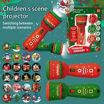
This week, I learned about embedded programming. A key decision I had to make was choosing the microcontroller and the programming platform for my final project. Since I am completely new to this field, I decided to go with a combination that many of my colleagues have recommended and used before — this way, I can focus on mastering it sufficiently to complete my project successfully. Ultimately, I chose to work with the SEEED Xiao RP2040 microcontroller, programmed using Arduino IDE. From here, I needed to carefully plan the number of functions my final project would require, ensuring that the microcontroller would have enough input and output pins available. After discussing with Mr. Steven Chew, we identified three main functions for my final project: o Music playback — Either a traditional mechanical style using a drum and pins or playing music tracks through external media. o Photo-screening function — Using a kids' torch projector (as mentioned in the previous week's plan). o Lighting effects — Either an internal lighting feature, an external one, or possibly both integrated into the final design. With these functions clearly defined, I now have a much clearer and more realistic vision of how my final project will come together.
WEEK 05 – LEARN TO DESIGN PRINT-IN-PLACE HINGE
Ever since I joined the Singapore Polytechnic FabLab, 3D printing has been one of the topics I was most excited to explore. One question that always intrigued me was: "How can a hinge be 3D printed in a single build without requiring any assembly?" It wasn’t until one of my students introduced me to the concept of "Print-in-Place" that I finally understood — what once seemed impossible was actually very much achievable! Since I have yet to finalize the exact size of my musical box, I used this week's learning to better understand the critical details I need to consider for my final project — such as: o The gap between hinges, o The number of hinges needed to properly support the screening panel, o And the structural considerations needed for reliable movement. Additionally, I realized that 3D printing will play an essential role in creating all the miniature models I plan to include inside my musical box — although the final theme is still yet to be decided.
WEEK 06 – MODELLING MY FINAL PROJECT
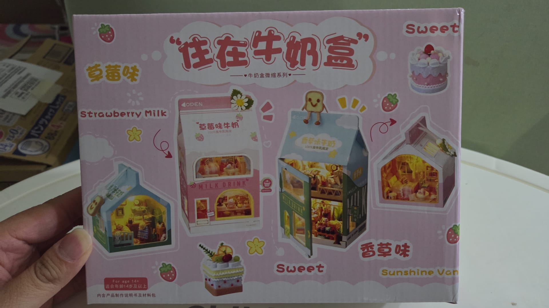
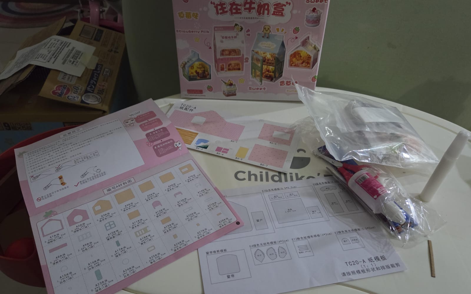
Although this week’s focus was on electronic design, with my current limited understanding — particularly regarding component usage, interconnectivity, and selecting suitable parts and models for my final project — I decided to shift my efforts towards modelling a simple structure for my project instead. To spark some inspiration for the visual design, I purchased a miniature model kit from my daughter’s art class, which gave me new ideas for how the final project might look. Building this model helped me visualize the potential layout and structure of my final project, and it also gave me a better idea of where and how the necessary electronic components could be integrated to bring the design to life.
WEEK 07 – TRIMMING DOWN THE DESIGN AND FINALIZING THE THEME FOR MY MUSICAL BOX
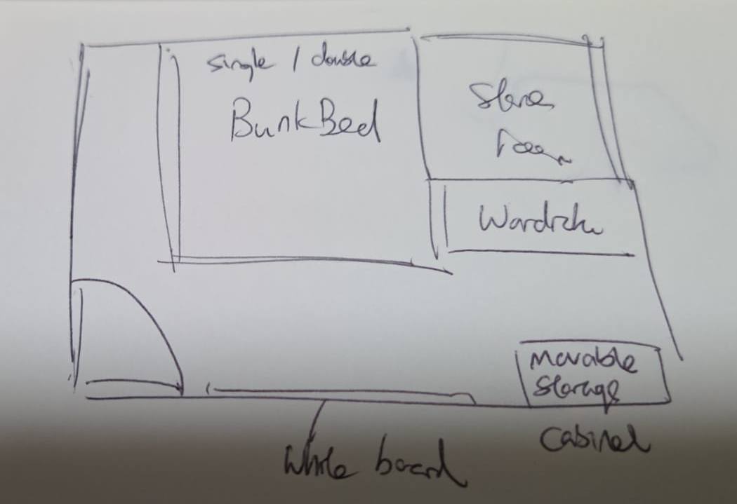
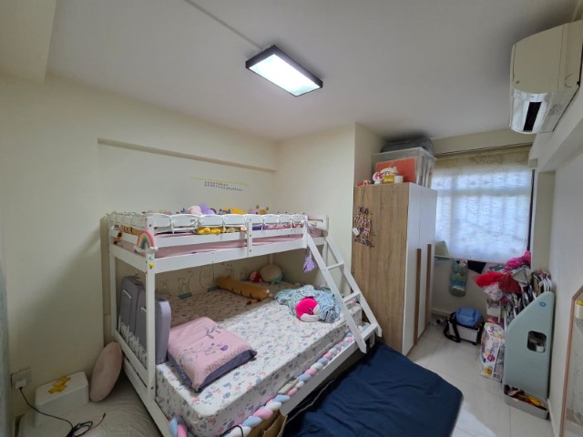
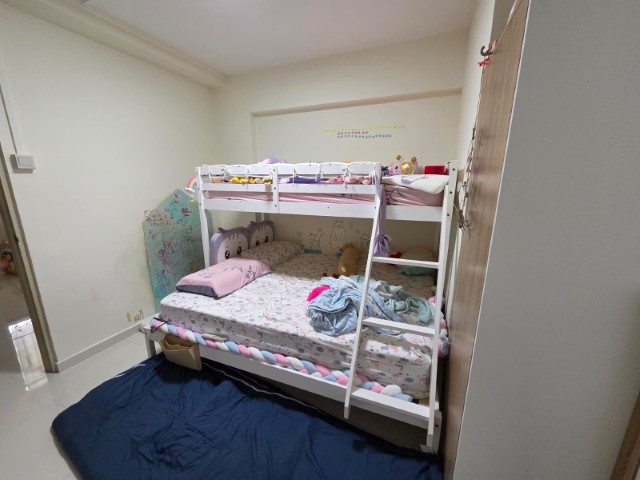
Since I already knew that my final project would not be something large or complicated, I spent this week refining and simplifying the design ideas to help me finalize the theme I wanted to pursue. I decided to create a miniature bedroom scene inspired by my two daughters — a small, cosy, and heart-warming bedroom that also includes a tribute to my wife, who always stays by their side at night to accompany them to sleep. Here is the draft plan view of my daughters's bedroom. Once the concept was clear, the rest of the planning started to flow more naturally — from the overall design layout to the selection of parts, and even the miniature models that I would 3D print to complete this tiny, personal bedroom project.
WEEK 08 – SKIP FOR A WEEK
This week has been particularly challenging for me, as I focused on preparing to create my own printed circuit board (PCB). Since I’m still struggling with circuit design and hands-on soldering skills, I dedicated extra time and effort to improve and familiarize myself with the processes — all in order to keep up with the tight timeline for completing my final project. As a result, there hasn’t been much visible progress made on my final project this week, but the learning and practice have been essential steps toward achieving it.
WEEK 09 – EXPLORING INPUT DEVICES
This week, I learned about input devices. I began thinking about which input method I should use for my final project to control and toggle the required functions. At the basic level, I only need a few push buttons to trigger different output actions. However, I have yet to finalize exactly how many switches will be necessary. Instead of using traditional physical buttons, I’m challenging myself to replace them with touch-sensitive pads, aiming for a sleeker and smoother final project surface. To achieve this, I am pushing myself to understand and master the concept of STEP RESPONSE, especially since we are not allowed to directly use a capacitive touch sensor module as a simple switch.
WEEK 10 – DETERMINING OUTPUT DEVICES FOR MY FINAL PROJECT
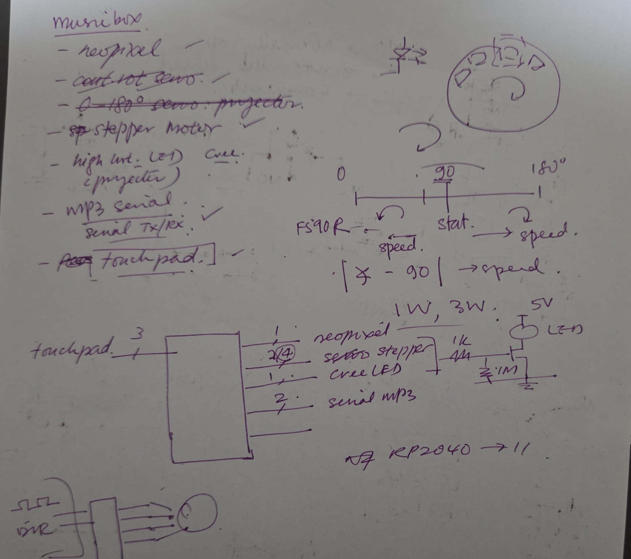
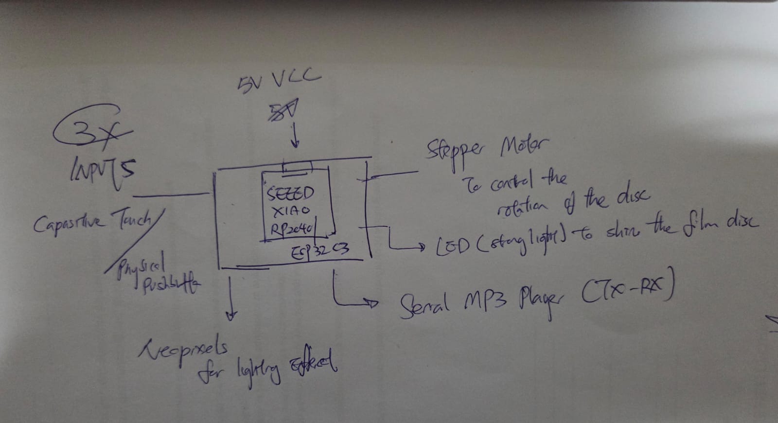
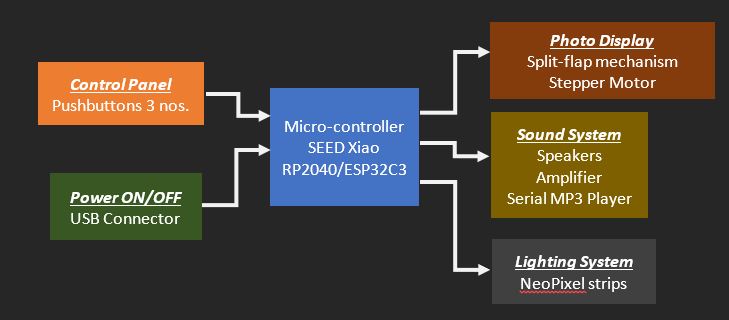
Following last week's decision on the input devices for triggering my project functions, this week I focused on finalizing the output devices needed to complete my final project. One major concern was the number of available GPIO pins I have. To clarify this, I consulted my instructor, Mr. Steven Chew. Here’s a summary of the pinout allocation: * Output Devices: o Neopixels (for lighting the music box) – 1 pin. o Bright LED (for projecting photos) – 1 pin. o Stepper Motor (to rotate the photo disc) – 2 or 4 pins. o Serial MP3 Player (for music playback) – 2 pins (must use Tx-Rx ports). * Input Devices: o Button Switch (for lighting control) – 1 pin. o Button Switch (for controlling both the bright LED and stepper motor) – 1 pin. o Button Switch (for MP3 player control) – 1 pin. In total, the pinout usage adds up to 11 pins, which fits perfectly with the available pins on my PCB. Based on this breakdown, I have started procuring the required components together with my Fab Academy partner, Florimond Chu, and began preparing my initial project modelling. Diagram below shows my initial system integration to make a musical box:
WEEK 11 – DILEMMA: WIRELESS CONTROL VS. PHYSICAL BUTTON SWITCHES
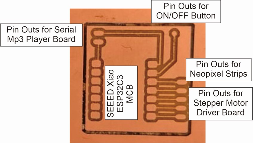
This week's topic focused on wireless control. For the individual assignment, I created a second PCB using the SEEED Xiao ESP32C3 micro-controller to meet the networking requirements, instead of modifying my first PCB (which uses the SEEED Xiao RP2040) that would have needed extra external components for compliance. Given that more physical contact points increase the risk of cable connection failures, I began considering the use of wireless remote control to manage the ON/OFF switching of my output devices. By doing so, I could free up the three PINOUTS initially reserved for button switches and potentially reassign them to other output functions if needed. For this week's assignment, I will test the feasibility of wireless control and compare it to using traditional physical button switches.
WEEK 12 – STEP INTO STEPPER MOTOR CODING
This week, as part of the Machine Building assignment, I had the chance to work on programming a stepper motor—an important component for my final project. Our team set out to build a coin sorter, which required a motor to drive the separator that lifts and directs coins onto the sorting track. I was assigned to design the coiling mechanism at the start of the sorter, which also meant I was in charge of writing the code to control the stepper motor. After over a week of facing and solving various challenges, we successfully completed our coin sorter. Through this experience, I learned how to run the stepper motor at a constant speed. Moving forward, my goal is to refine the motor control so it can rotate in specific steps and stop precisely — something I’ll need for the rotating photo disc in my final project.
MIDTERM BREAK
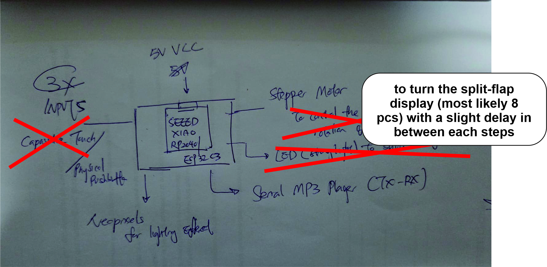
Although there were no scheduled classes this week (as it was mainly reserved for machine building), I didn’t take that as a chance to slack off. Instead, I focused on planning the system integration for my final project—a musical box. One of the key features involves displaying memorable photos. Originally, I had planned to use a simple LED projection method, but I came across a more creative and engaging alternative: The SPLITFLAP DISPLAY!. I instantly felt that this approach offered a more tangible and charming way to showcase my photo memories.
Aside from this update, the rest of the features remain the same: I will use a Serial MP3 Player to play songs and a Neopixel strip to add lighting effects. For inputs, I’ve planned to include three pushbuttons, as outlined in my Week 10 final project planning. Here is how my system integration has been revised after the change made on this week:
WEEK 13 – MOULDING AND CASTING SOMETHING
With limited time left to explore the remaining weekly assignments and also to review and refine previous tasks — both my individual work and the group project with my Fab Academy partner, Florimond Chu — I decided to use this week’s assignment to create button casings for my physical pushbuttons. This objective guided the direction of my moulding and casting process. The photo below is taken from my Week 13 individual assignment.
WEEK 14 – 3D PRINTING SAMPLE MODELS AND FINALIZING DESIGN OUTLOOK
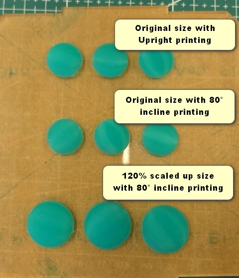
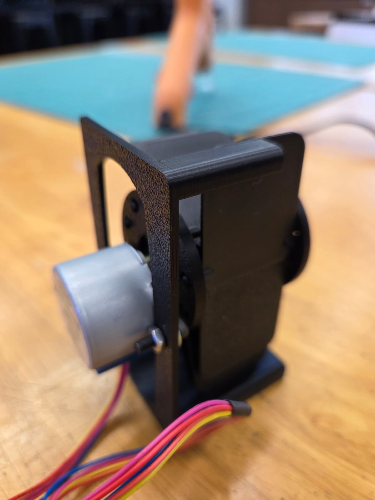
After finalizing the concept of the split-flap display, I visited the MakerWorld website to explore existing models suitable for physical prototyping. By searching “split-flap display,” I discovered a practical design that uses a stepper motor instead of manual cranking. The model, titled “Simple Split Flap Display by Chipmunk54”, ), was chosen for 3D printing. It features a 28BYJ-48 stepper motor, and I tested it using a sample Arduino sketch previously used in my coin sorter project:
Following the initial test, I modified the design by extending the flap length from 35mm to 65mm—nearly doubling it. This was to evaluate the stepper motor’s capability to handle increased load and to observe stability while rotating (as longer flaps contribute more weight to the drum mechanism). See video below for the updated trial:
From the results, I realized that I may need to include a cantilever support on the opposite end of the drum to prevent sagging and minimize vibration during operation. Next, I began planning the overall dimensions of the musical box, guided by the following considerations: • Optimal photo display size – to determine the final dimensions of the split-flap assembly. • Component sizes – including the custom development board, speaker, Serial MP3 player, and 28BYJ-48 stepper motor – to estimate the internal "storage space" required. • Cable routing – to ensure clean wiring from the storage area to each component, and to avoid a tangled or cluttered setup inside the box.
WEEK 15 – FINALIZING SYSTEM DIAGRAM AND INTEGRATION
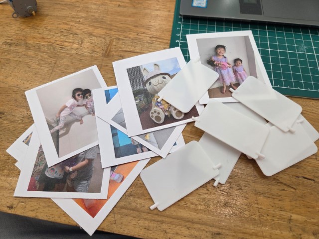
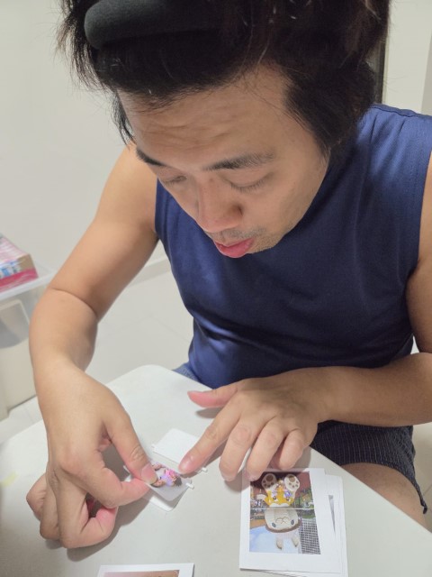
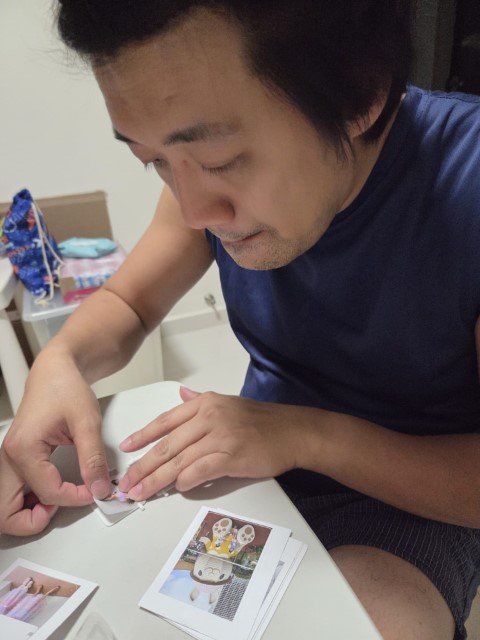
As outlined in the Week 15 assignment, we were required to present a clear system integration plan to our instructors, who would assess our readiness to complete the final project in time for the presentation deadline. Much of the work this week builds upon what I’ve previously documented in my Week 15 Individual Assignment. My final project integrates mechanical, electronic, and software components into a cohesive, functional system: • Mechanical System > Split-Flap Mechanism: A rotating drum with printed photo cards that flip mechanically. > Stepper Motor: Provides precise, controlled movement to rotate the photo display. > Frame Structure: Constructed using 3D-printed parts, acrylic, or plywood to house all components securely. • Electronic System > Microcontroller (SEEED XIAO RP2040): The core controller that manages all functionalities. > Stepper Motor Driver: Powers and controls the rotation of the split-flap display. > NeoPixels: Provide ambient lighting effects corresponding to the selected photo or mood. > Serial MP3 Player Module: Plays music tracks based on user interaction. > Physical Pushbuttons: Allow users to interact with the system (e.g., change photo, play music, toggle Neopixels). > Power Supply: Powers the stepper motor, Neopixels, MP3 player, and controller. • Software System (Firmware) > Motor Control Logic: Utilizes libraries like AccelStepper for precise rotation. > Audio Playback: Sends commands to the MP3 player to play audio from the SD card. > LED Control: Uses the NeoPixel library to produce lighting effects. > Input Handling: Reads button presses to trigger various actions. > Debounce Logic: Ensures accurate and reliable button detection. • System Flow Overview > User presses a button. > Microcontroller responds by: > Activating the stepper motor to rotate the split-flap. > Playing a music track via the MP3 module. > Lighting up the NeoPixels with ambient effects. > The system then waits for further user input or automatically resets after the music ends. Given that I have only 27 days to complete the project, I have drafted a time plan as follows: 1. 15th May – 18th May: a. Finalize the Bill of Materials (BOM) and component dimension table. b. Design and 3D print the negative mold for the pushbutton membrane (moulding and casting). 2. 19th May – 25th May: a. Design and fabricate a custom PCB tailored for this project. b. Begin integrating individual systems and developing the remaining code. c. Print stickers for photo cards used in the split-flap module. 3. 26th May – 1st June: a. Assemble all components into the final musical box frame. b. Upload all firmware and perform a full system test run. Throughout this period, I must consistently capture photos and videos of each step as part of my documentation. These assets will be essential for creating the required 1-minute video and 1-page project poster for the final presentation.
Inspired by my deep passion for music, I have always dreamed of creating my own music box—something unique that I could design and build from scratch. To ensure originality and avoid any copyright concerns, I began researching existing products and found a creative niche: a photo-screening music box. Before diving into the design phase, I gathered insights from various sources, including Fab Academy archives, online maker forums, and previous student projects. To size components accurately, I referred to datasheets and consulted with my instructor, peers, and SP FabLab alumni for technical guidance. My full Bill of Materials (BOM) are shown as below:
COMPONENT
MODEL NUMBER
QTY
COST
PURCHASE FROM
REMARK
Stepper Motor
28BYJ-48
1 set
$6.40 (price from Kuriosity)
Lab Inventory
With Motor Driver Board
NeoPixel Strip
144LEDs/M 1M - IP30 White PCB
100 mm Length (top + bottom)
$7.63
Lazada - WNPQKC Shop
N/A
Serial MP3 Player
YX5300 UART Control Serial MP3 Music Player Module
1 pc
SG$6.71
Shopee - zwinz1aa.sg
N/A
PushButton
Momentary Pushbutton Switch - 12mm Square
3 pcs
$2.25
Lab Inventory
N/A
SEEED XIAO RP2040 micro-controller board
1597-102010428-ND (Digikey)
1 pc
SG$10.00
Lab Inventory
N/A
1.75mm PLA+ 3D Filament
Bambu Original Filament
Depends
$51.00
Lab Inventory
Various colour
3mm Acrylic/Plywood Board
N/A
Depends
N/A
Lab Inventory
N/A
Printed Sticker
AVS Technologies Pte. Ltd.
Depends
N/A
Lab Inventory
Matte surface finishing
1W 8ohm Speakers
N/A
1 pair
N/A
Lab Inventory
DIY Speaker Kit
Bolts, Screws and Fasterners
N/A
Consumables
N/A
Lab Inventory
N/A
FR1 Copper Board
N/A
1 piece
$1.00
Lab Inventory
N/A
5V AM8406 Digital Amplifier Board DIY Small Speaker 5W+5W Dual Channel Stereo Amplification Module
3.5mm Auxiliary Audio Jack to Jack Cable 90 Deg Right Angle
UGREEN
1 piece
$3.96
LazMall - UGREEN
N/A
The accompanying block diagram outlines all the parts and systems developed as part of this final project. Being part of the SP FabLab team gave me a significant advantage—I had access to a wide range of digital fabrication tools and hands-on experience. The main processes I used included: • 3D modelling (Fusion 360). • 3D printing. • Laser cutting. • PCB design and production. • Arduino programming. • Web documentation. While planning the fabrication workflow, I also identified key technical questions I needed to address, as outlined in Week 17 assignment. By the time I reached the two-thirds mark of my Fab Academy 2025 journey, several parts and systems were already functioning: • Individual code development for the stepper motor, NeoPixel lighting, and MP3 playback. • A working split-flap mechanism. • A complete interlocking housing structure. However, a few elements were still in progress or undergoing refinement: • Integrating all three functions into a single-button control system. • PCB production and power management optimization. • Cable routing and organization across different subsystems. Compared to the evaluation plan outlined in Week 17 assignment, my final project was assessed through slightly broader criteria: 1. Full functionality testing of all subsystems. 2. Project review by both local and remote Fab Academy evaluators. 3. Live demonstration during the final presentation. 4. User testing with my two daughters, who were the intended users. This project showcases how digital fabrication and electronics can be merged to create an emotionally meaningful and educational product. It also sets the stage for further development in areas like interactive learning tools, personalized memory boxes, and affordable mechanical display systems for use in education, therapy, or creative storytelling.
WEEK 16 – WILD CARD WEEK
Although this week is designated as a "Wildcard Week," which allows students to explore something outside the standard syllabus, it's easy to get side tracked from the final project. However, this wasn’t the case for me and my Fab Academy partner, Florimond Chu. Initially, we considered experimenting with biomaterials—something I had learned during the FLA Pilot Course two years ago. But after discussing our priorities, we both agreed to focus on learning embroidery instead, as it’s a relatively simple skill to pick up and requires less time to complete both the final output and the documentation.
Everything was under control!!!
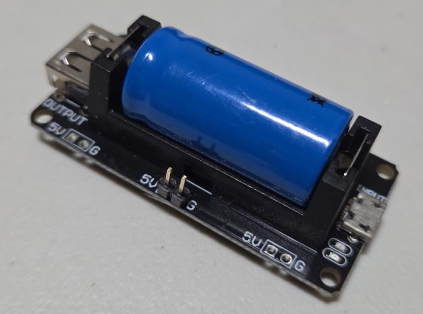
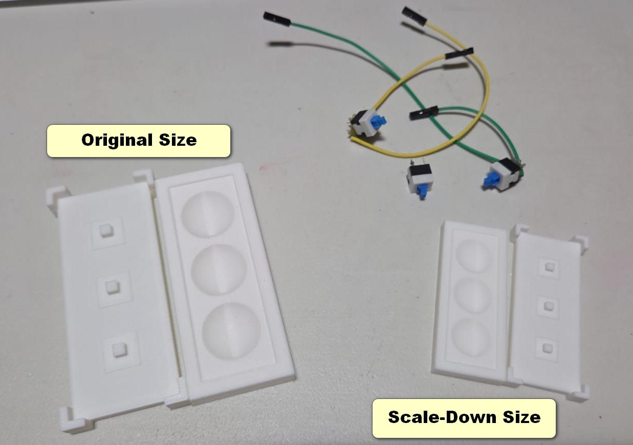
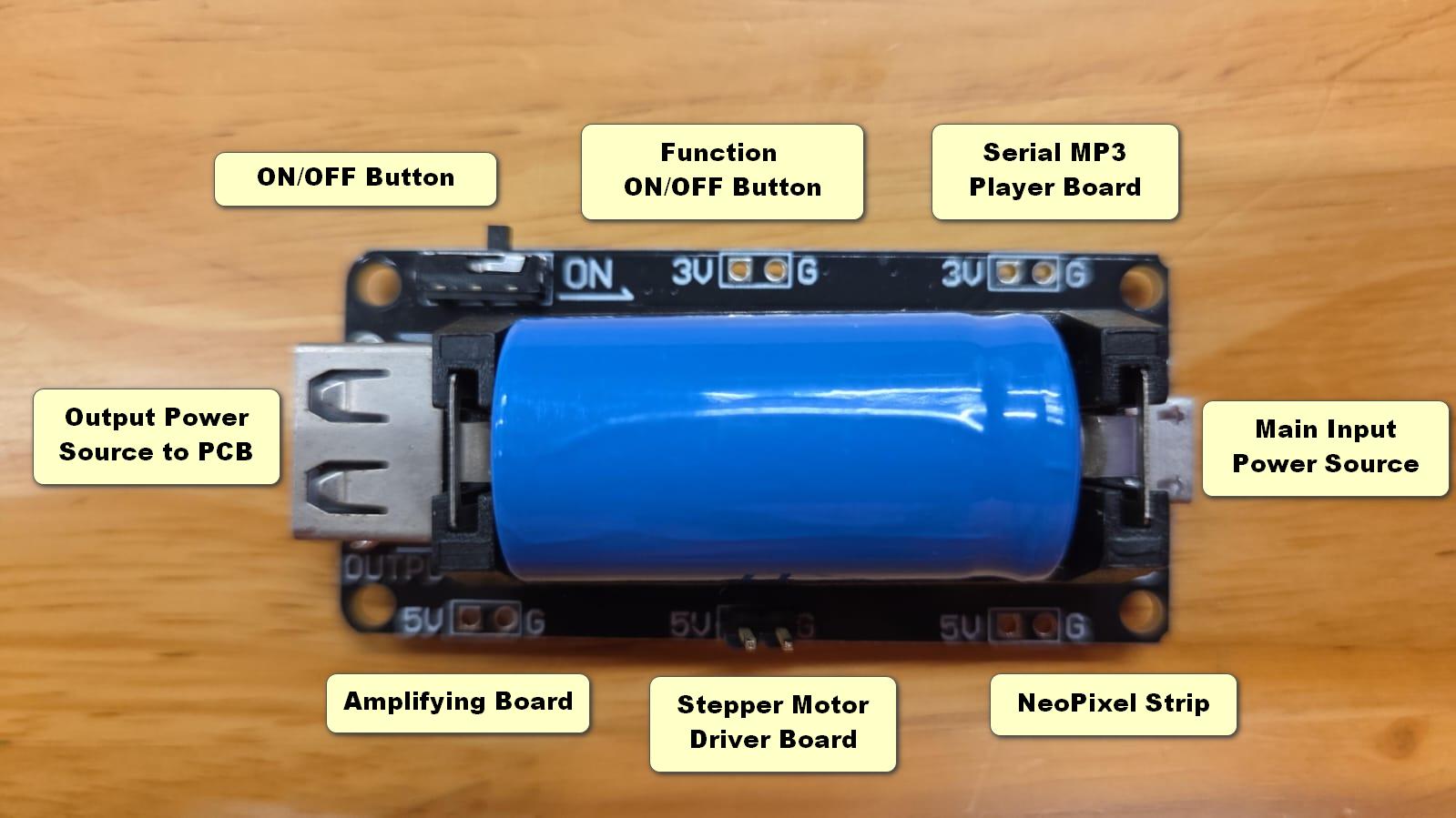
I managed to complete the Week 16 individual assignment in just three days: Thursday for the tutorial, Friday for the practical session, and Saturday for documentation—making it the quickest assignment I’ve completed since the course began. With time to spare, I used the rest of the week to continue designing my musical box. Two major design changes were made this week: Instead of using a bulky power bank, my FabLab alumnus Zi Hon suggested switching to a Li-Ion battery board, which is much more space-efficient and better suited for my compact music box. I also changed the buttons used as input devices. The original buttons were too large and affected both my mold design and internal space planning. To address this, I redesigned and reprinted a new set of hard-negative molds, scaling down the original version by 33%.
WEEK 17 – FIRE-FIGHTING MODE SWITCH ON!!
As scheduled in the timeline above, I’ve made significant progress on my final project. Out of the three planned tasks, I’ve successfully completed the sticker printing for the split-flap photo-screening system and the individual coding for each of the three main functions. I have intentionally postponed the PCB production to the final phase, as the layout and positioning of all components need to be finalized beforehand.
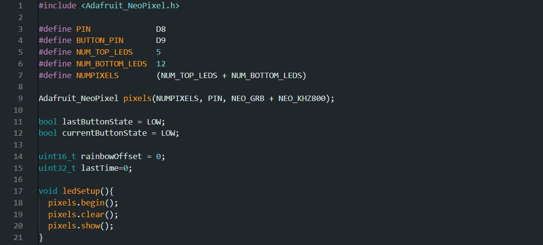
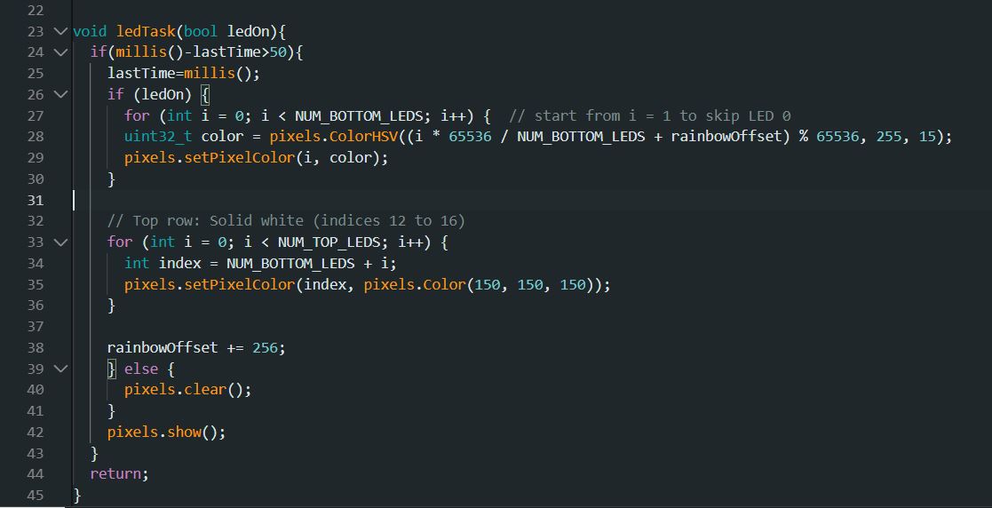
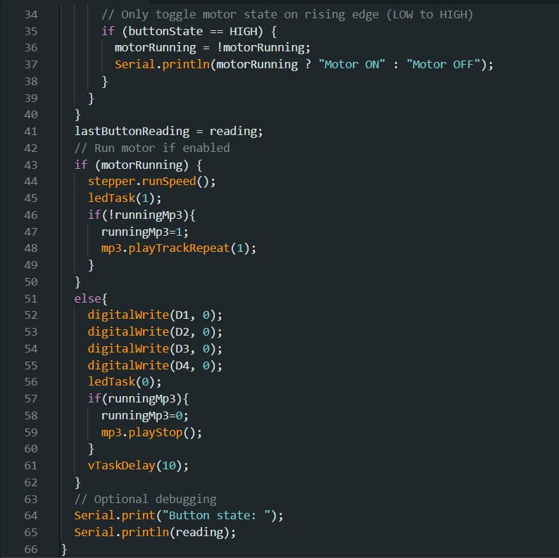
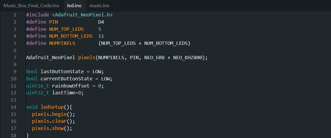
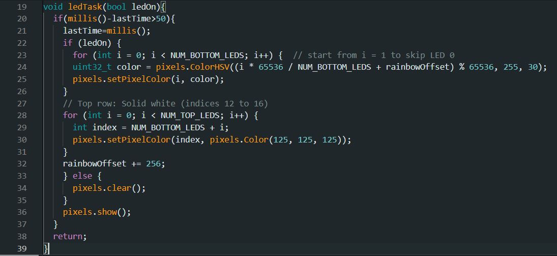
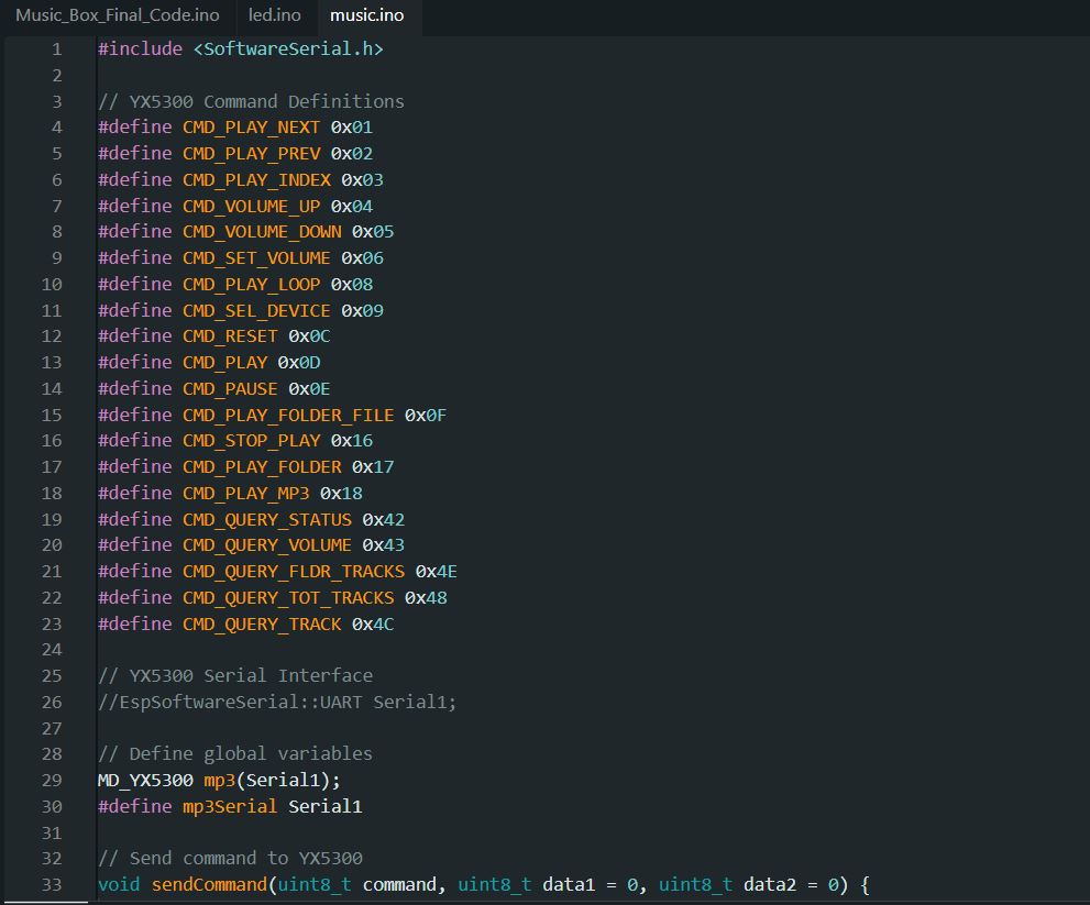
For the coding tasks: • I reused and adapted the stepper motor code from Week 12’s Coin Sorting Machine project for the split-flap mechanism, ensuring consistent and smooth rotation. • With help from ChatGPT, I developed a custom program for the NeoPixel LED strip, which is divided into two rows with different purposes: o The top row (4–5 LEDs) emits a bright white light to illuminate the photos. o The bottom row (12–13 LEDs) creates a soothing ambient effect using a slow rainbow animation. • For music playback, I referred to a sample code provided by my local instructor, Mr. Steven Chew, during Week 10 – Output Devices. You can access the documents HERE.
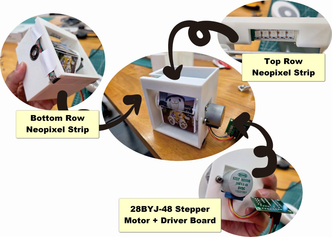
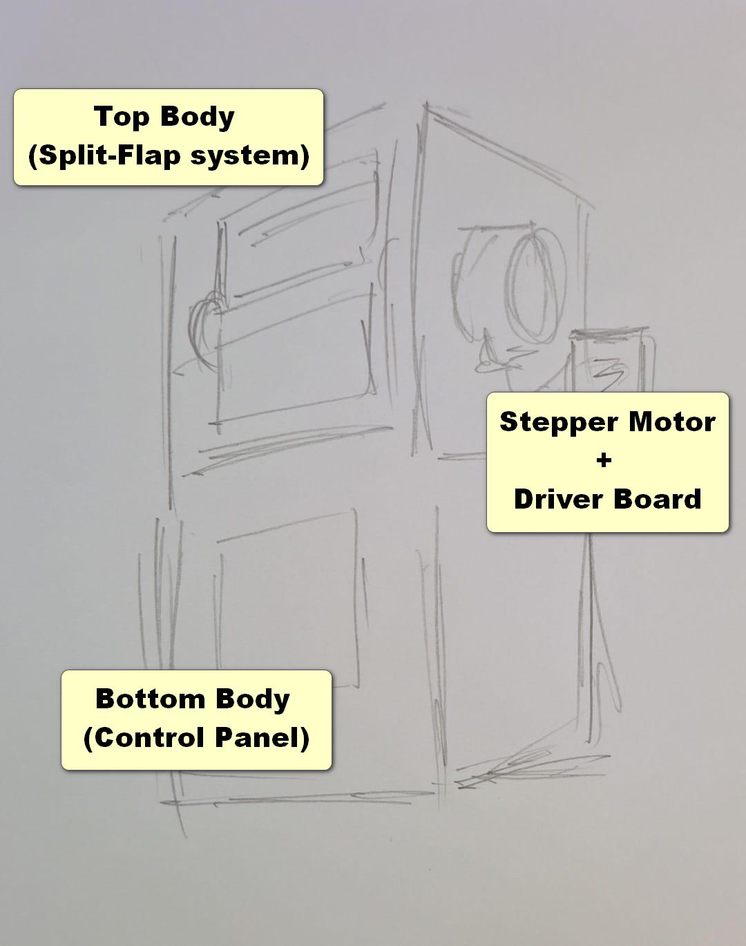
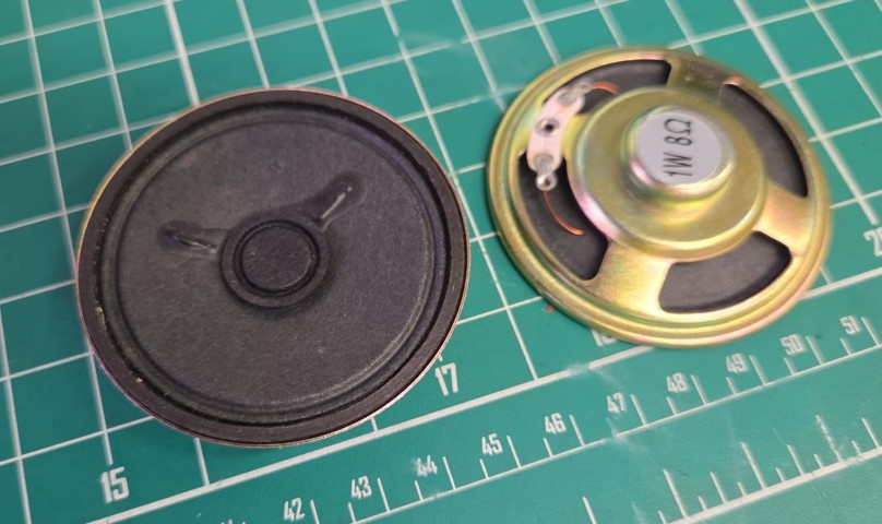
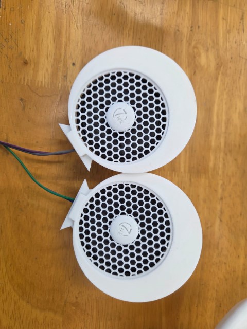
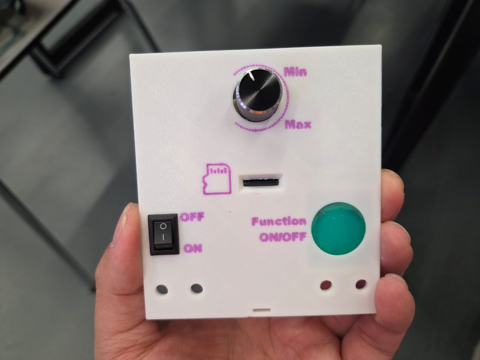
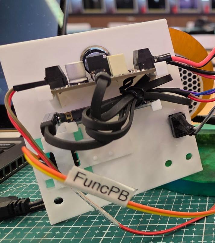
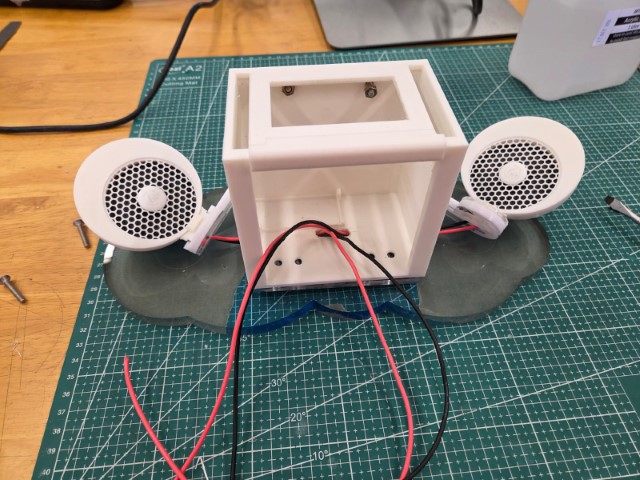
Most of my lab time was dedicated to 3D modelling and designing the housing structures for various subsystems: 1. Split-Flap System (Photo Screening) Two critical considerations shaped the design of this frame: • Motor placement (height and orientation) to maintain a level rotation plane for smooth flap movement. • The physical enclosure design to: o Securely mount the NeoPixel strip above the flap. o Prevent the flaps from collapsing before displaying the upper part of the photos. 2. Control Panel Housing Once the split-flap mechanism was finalized, I shifted focus to the control panel, which includes: • An ON/OFF switch. • A toggle button. • A MicroSD card slot. • A volume control knob. Initially, I planned to place the entire control panel behind the split-flap system, as shown in my second self-drawn draft from Week 15. However, this approach proved impractical. Based on Mr. Steven Chew’s advice, I revised the layout to place the control panel at the bottom front of the split-flap system. This provided two key benefits: • Improved user accessibility for operating the controls. • Raised the split-flap mechanism for better photo visibility. 3. Speaker Assembly Initially, my partner Florimond Chu and I tested a set of compact speakers, but they didn’t deliver adequate sound quality. We eventually switched to a more suitable speaker type, shown in the photo below. Although the new speakers disrupted my original placement plan due to their larger size, Florimond proposed an innovative solution—integrating the speaker housing into the “BIG EARS” of a Mickey/Minnie Mouse design. This not only resolved the space issue but also added a playful and child-friendly appeal, especially meaningful as I have two young daughters. 4. Button Inputs Originally, I intended to use three buttons to control individual functions. However, due to defects in two of the silicone button caps — caused by air bubbles during casting — I decided to simplify the system. I replaced the three-button setup with a single multi-function button. Now, after switching the main power ON, one button press activates all three systems (split-flap, music playback, and lighting). This change: • Streamlines the user experience. • Reduces code complexity. • Shrinks the overall footprint of the music box. 5. Internal Frame for Component Placement My original plan was to mount all internal components—such as the amplifier board, Serial MP3 module, custom PCB, and battery pack—on the rear wall of the enclosure. However, considering user accessibility, some elements were relocated to the front panel, particularly those that require frequent interaction. 6. Front Control Panel Design Several factors were considered when designing the front cover: • The knob clearance for the volume control (amplifier board). • Easy access to the MicroSD card slot. • Secure mounting for both the button cap membrane and pushbutton. • A clean, ergonomic panel layout for intuitive control. This iterative design process has significantly refined the functionality and user experience of my photo-screening music box. With thoughtful integration of electronics, mechanical systems, and user interaction elements, I am confident the final prototype will showcase both technical competence and creative design.
In parallel with developing my final project, I had to complete one outstanding weekly assignment before the submission deadline on 4th June 2025. According to Fab Academy requirements, students must achieve 100% completion of all weekly assignments, with each task verified by their local instructors in order to qualify for graduation. Additionally, I revisited several earlier assignments to implement feedback given by my instructors, ensuring each one met the full completion criteria. To manage this, I allocated 2–3 full days solely for updating assignments before continuing work on my final project. Beginning Week 18, I focused on refining and documenting each section of the project. I divided my time between adjusting 3D models for fabrication (laser cutting and 3D printing) and writing technical documentation. A key area of focus was designing the mechanical interlocking system, logical assembly flow, and ensuring tidy cable management throughout the build.
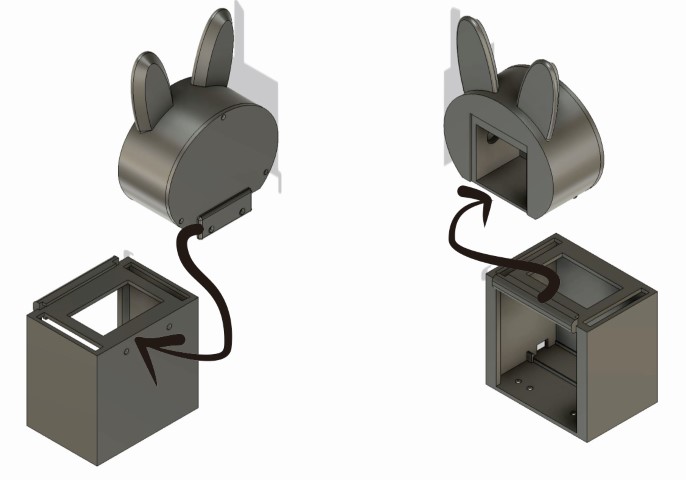
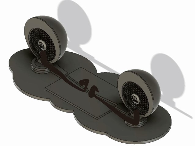
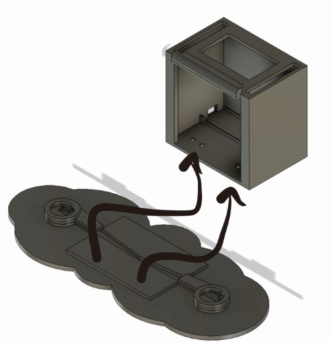
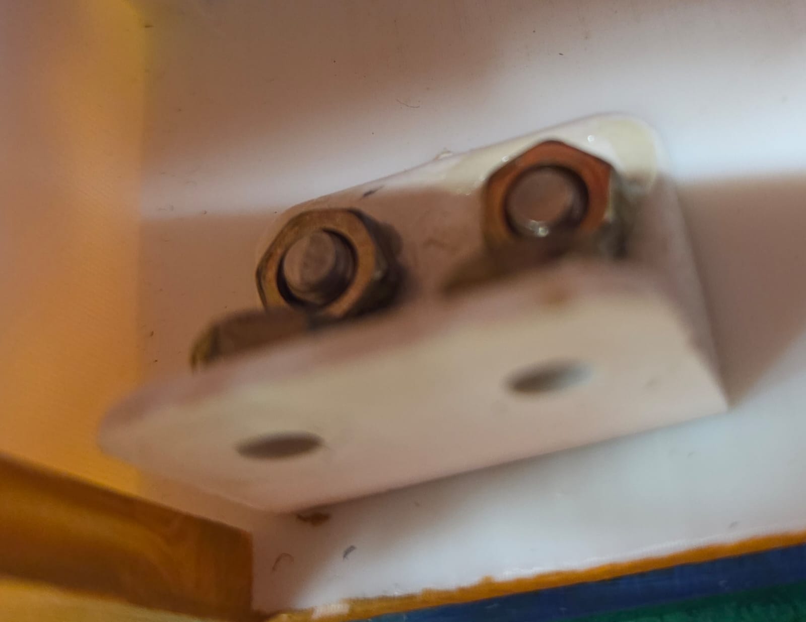
Mechanical Interlocking System
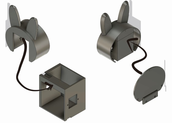
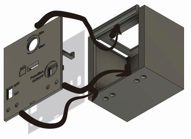
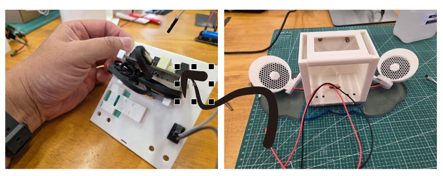
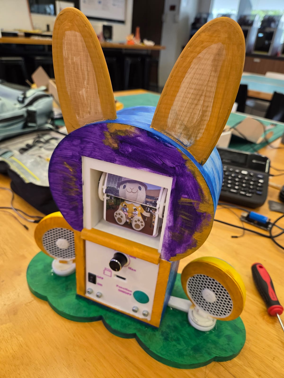
• Cover for Stepper Motor and Driver To conceal the exposed 28BYJ-48 stepper motor and its driver board, I needed an enclosure that provided balanced coverage from all sides. My Fab Academy teammate, Florimond Chu, proposed a speaker mount resembling Mickey Mouse ears, inspiring me to transform the enclosure into a character head. Originally conceived as a mouse face, the design evolved into a bunny head due to changes in speaker dimensions and weight distribution. This revised enclosure not only housed the stepper motor and driver but also integrated NeoPixel strips along both the top and bottom sections. • Connecting Upper and Lower Sections To securely attach the split-flap mechanism (upper section) to the main body frame (lower section), I designed a C-channel on the top surface of the lower body, allowing the upper body to slot in firmly. A rear extension plate on the upper assembly acts as a mechanical lock, creating a "sandwich" joint that prevents accidental detachment. • Front Control Panel Cover To ensure easy access for troubleshooting internal electronics, I designed a removable front panel using a slot-and-bolt system: • A 2.5mm-deep groove at the top allows the panel to slide into place. • The bottom edge is secured with PVC L-brackets, fastened using bolts and nuts. • A 7mm gap at the bottom edge allows the panel to be pried off easily when needed. • Speaker Mounting and Cable Routing After deciding to move the speakers from the upper to the lower body (now serving as the “feet” of the bunny), I designed a cable routing path to maintain neat wiring: • A 45° inward-angled slot at the base of each speaker holder guides wires inward. • These paths lead into a trunking channel that connects to the main body. • Two holes were created on the base of the bottom body to allow speaker wires (2 per side) to enter and connect to the amplifier board mounted behind the front panel. • Securing the Assembly to the Base Plate To anchor the entire structure to the laser-cut base plate, I reused the same PVC L-brackets from the control panel fixings. I drilled four through-holes into the base plate and used M4 x 15mm countersunk screws to fasten the main body securely.
Electrical and Electronic Cable Management
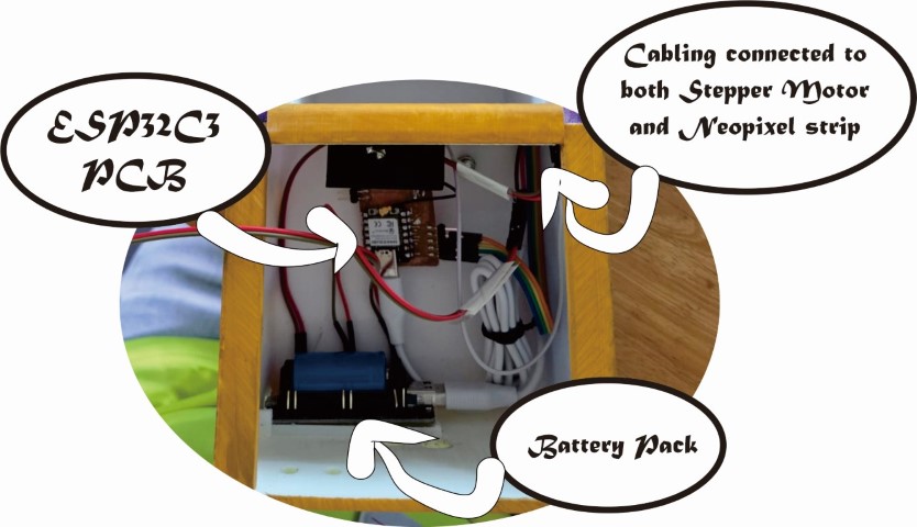
• Upper-to-Lower Body Cable Passage A total of 9 wires descends from the upper body: • 3 for the NeoPixel strips. • 2 for 5V power. • 4 for data and power lines to the motor driver board. A dedicated opening slot was designed to allow these cables to pass cleanly from the upper to the lower body. • Internal Layout of Battery Pack and PCB The position of both the battery pack and PCB dictated the internal cable routing. The PCB design was customized to match the input location of each connected component, minimizing excess cable slack inside the main body. • Control Panel Wiring The front control panel houses most of the interactive electronics. To ensure serviceability, I factored in an extra 50% cable length for all components mounted on the panel to provide sufficient slack. Additionally, I direct-soldered wires to header pins to avoid accidental disconnections when the panel is closed. • Speaker Cable Trunking The two speakers located on the sides of the main body route their wires through acrylic trunking made from 3mm sheets. To avoid wire tension caused by the 45° inward-angled speaker holders, I extended cable length by an additional 10% on top of the original 50% allowance (due to access panel flexibility). This ensures the system avoids cable strain or breakage over time.
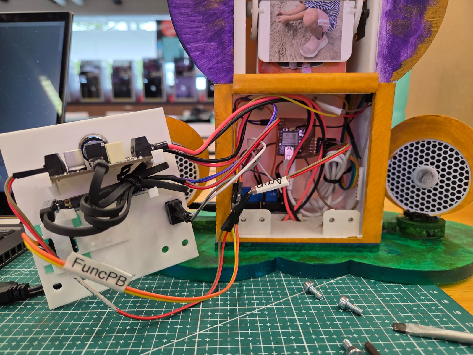
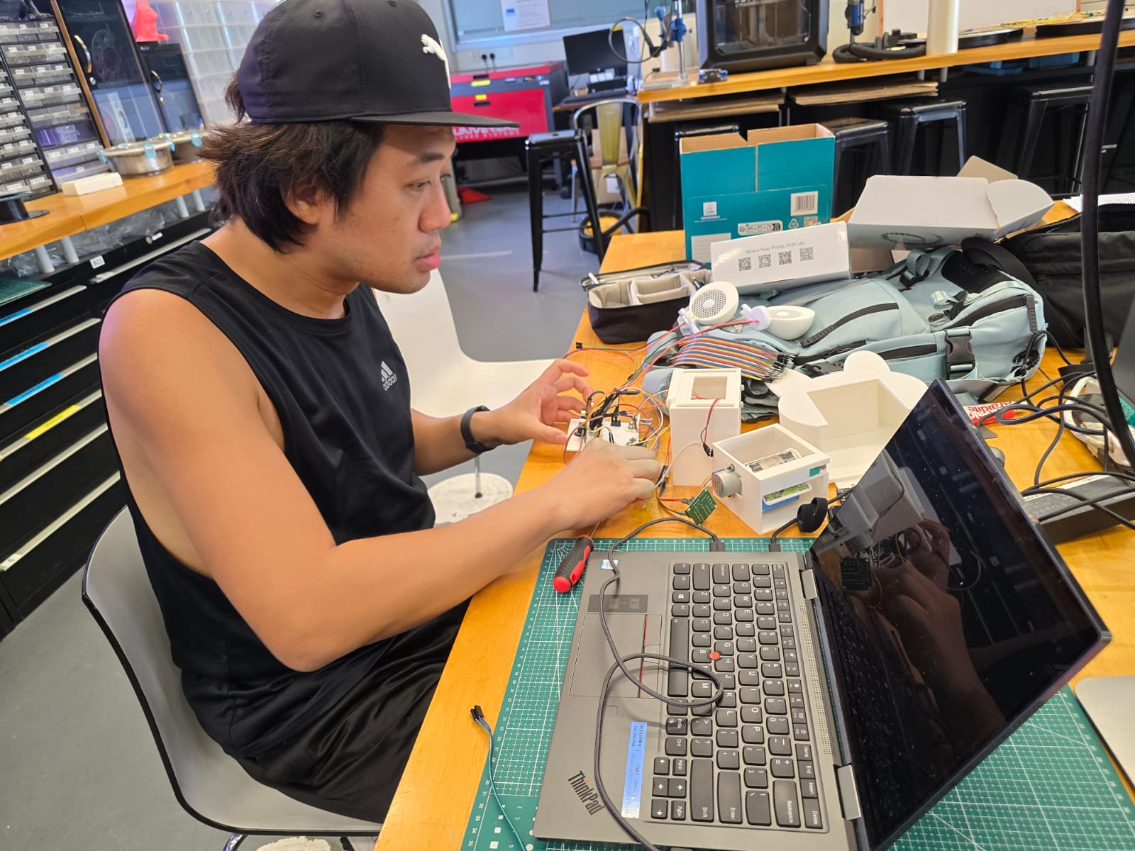
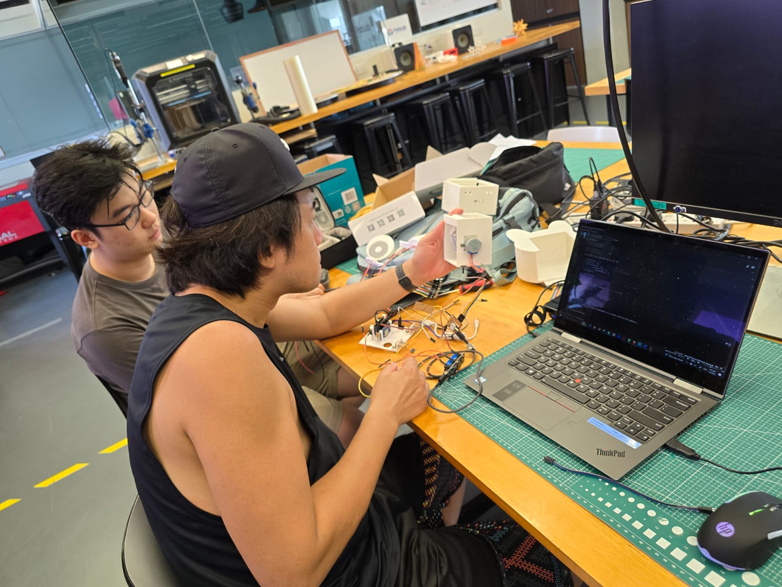
After finalizing the mechanical aspects of the music box, I shifted my focus to coding for the final project. Due to the imperfect fit of the silicone button caps, I had to revise my initial plan of using three separate buttons to control three different functions. Instead, I opted for a single-button toggle system to manage all three. In hindsight, this actually simplifies the user experience—especially since my intended testers are my daughters, making it easier for them to interact with the prototype. To consolidate the functionality, I sought help from SP Fablab alumnus Zi Hon, who assisted in merging three separate code segments: • The stepper motor control from Week 12’s machine-building assignment, • The NeoPixel lighting control for both top and bottom strips, and • The Serial MP3 player code, provided by Mr. Steven Chew, my local instructor. While Zi Hon worked on the combined code, I began assembling the system using all available components to test the code functionality in real-time with actual hardware. During initial testing, a few expected issues emerged: 1) Cable congestion around the Li-Ion battery pack and temporary PCB setup. 2) Inaccurate cable length estimations for components placed behind the front cover (primarily the sound system and button). 3) Power consumption concerns when all features—motor, lights, and audio—are running simultaneously. All these issues must be addressed by 8th June 2025, to leave sufficient time for preparing the presentation slides and demo video.
PCB Production
Two early design decisions significantly simplified the PCB production process: 1) Reducing the number of button inputs from three to one decreased the number of pin headers required on the board. 2) Choosing a Li-Ion battery pack streamlined power management and resolved previous power supply limitations. Refer to the table below:
S/N
COMPONENT
5V/3V3/OTHERS
REMARK
CABLE TO PCB
01
Stepper Motor Driver Board
5V - GND
Direct solder from the battery pack
4 cables. Both end female-type connectors
02
Neopixel strips (Top and Bottom)
5V - GND
Direct solder from the battery pack
1 cable. Both end female-type connectors
03
Amplifying Board
5V - GND
Direct solder from the battery pack
N/A
04
ON-OFF button
Direct button source
Extended cable for front panel opening
N/A
05
Serial MP3 Player board
3V3 - GND
Female pin heads provided
2 cables (Tx-Rx). Both end female-type connectors.
06
Function Button
3V3 - DATA
Direct solder from pushbutton and extended.
1 cable. Both end female-type connectors
07
PCB
USB-A (5V)
USB-A to USB-C connector cable
Connect to Type-C connector on Seeed Xiao ESP32C3.
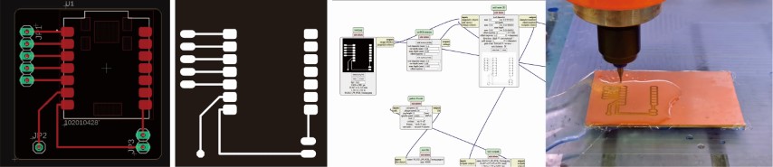
I have a clearer view on how my cable should route within the small 104.5mm(L)x69.0mm(D)x98mm(H) space, as well as how my PCB should be like. The process of creating the board is the same as those outlined in Week 6, so I won’t go too much into the process. With these 2 setups for the components, here is what my cable management will be looks like:
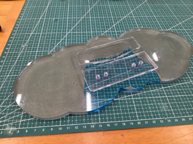
Base Structure for Main Body and Dual Speakers
Before attaching the two side-mounted speakers to the main body, I installed a 10mm clear acrylic base plate to provide overall stability. I also designed elevated platforms for both the main body and speaker assemblies. These raised sections allow the speaker cables to run neatly underneath the laser-cut components before entering the main body and connecting to the amplifier board. For the speaker bases, I secured them to the acrylic plate using epoxy adhesive. For the main body, I used PVC L-brackets with four M4 nuts glued to the inner side of each bracket. This setup allows the main body to be bolted securely to the base plate. The vertical edges of the main body also serve a dual function by acting as part of the locking mechanism for the front panel.
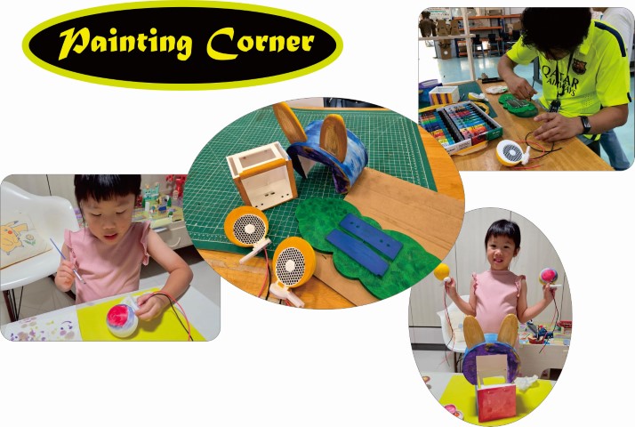
Aesthetic Finishing
Knowing that my elder daughter has a talent for art, I invited her to help paint the exterior of the music box. The result speaks for itself—the gradient and colour tones she applied turned out beautifully. I’m truly proud and grateful to have such an artistic daughter who could contribute to the final touches of the project.
Final Week – System Integration and Code Implementation
As I entered the final week — just before Presentation Week — I made sure all electronic components were properly secured using the custom 3D-printed parts I had designed. Once everything was in place, I proceeded to assemble the full system and perform a test run. With the assembly complete, I was able to mark this stage as done and move on to the final focus of the project: coding the complete functionality of the music box.
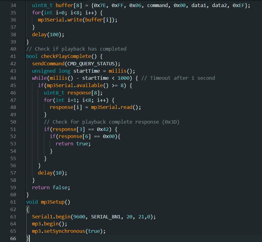
Coding for Music Box
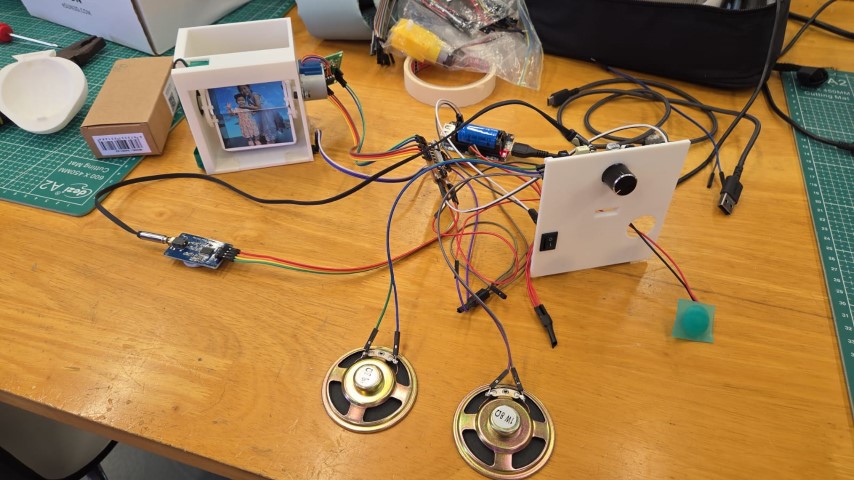
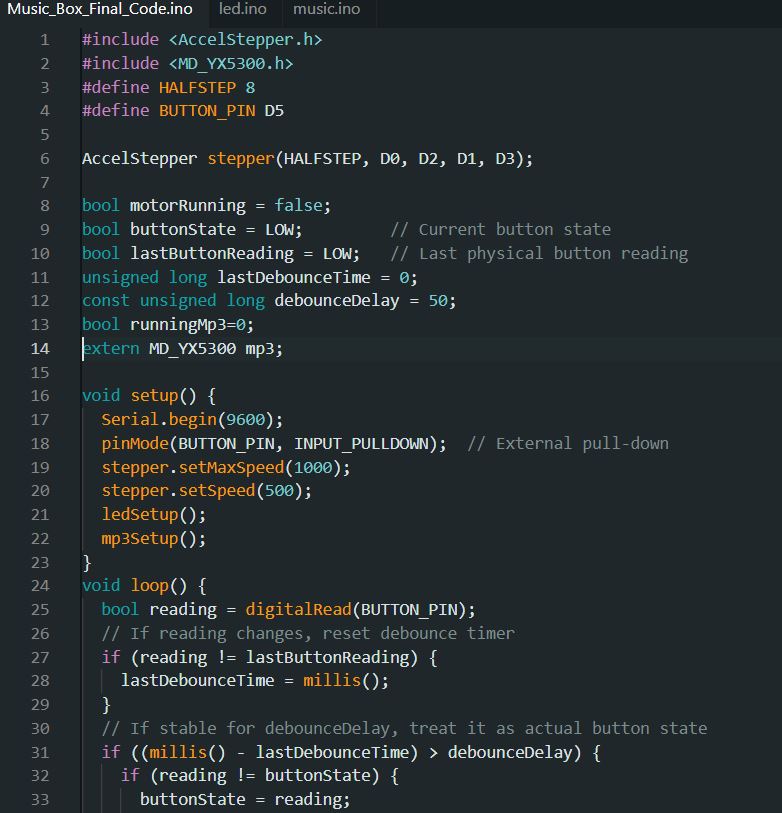
As mentioned back in Week 17, I simplified the control interface by reducing the input from three buttons to a single button. This made the code more streamlined, allowing one button to toggle all three functions simultaneously. With support from Zi Hon, an SP FabLab alumnus, I successfully integrated the three individual code segments—stepper motor control, NeoPixel lighting, and MP3 playback—into a unified program that operates all functions cohesively. Main code to run the stepper motor: NeoPixel strip code to have different lighting effect: Serial MP3 player code to read song tracks from MicroSD card. System testing with the final code:
Getting the final code to run the entire system smoothly wasn’t a straightforward process. The issues weren’t due to coding errors, but rather hardware connectivity problems, such as: 1) Incorrect wiring between VCC and GND. 2) Loose DuPont cable connections. 3) Insufficient power supply when running all three functions simultaneously—especially at higher audio volume. 4) Improper connection sequence for the stepper motor driver board. After several troubleshooting attempts...
Finally — Success! What a huge relief! After a thorough final check, I brought the completed music box home and invited my two daughters to be the first to try it out and have some fun with it.
On the Presentation Week
After collecting all the necessary materials—photos and videos—I spent some time preparing my project poster using CorelDRAW. For the video presentation, it was actually my first time creating a video. My Fab Academy buddy, Florimond Chu, recommended that I use Adobe Premiere Pro for editing. I dedicated two full days to arranging all the relevant content and sharing the journey of how I designed and built my very first product: the Lullaby Music Box. Fortunately, both Florimond and I were scheduled to present on the final day (13th June 2025), which gave me some extra time to rehearse and prepare for potential Q and A during the evaluation. My final presentation slides: And here is my presentation video:
ON 13th June 2025, 2130hrs
Special thanks to my FabLab colleague, Mr. Bartholomew Ting, for being sharp-eyed and capturing a short video clip of my presentation.
ON 13th June 2025, 2300hrs
At this moment, I could finally call myself a “Conditional Graduate” — right after the final student completed their presentation. I was overcome with a mix of happiness, exhaustion, and relief as I listened to Prof. Neil congratulating us all. • Happiness – Before enrolling in this course, building a music box felt like an impossible dream given my limited skills and knowledge. But over the past six intense months, I’ve acquired just enough know-how to design, model, fabricate, program, and assemble my very first self-made product. Honestly, it still feels unbelievable! • Exhaustion – I roughly calculated my average sleep over the last six months: just 4 hours a day. In the final two weeks, I barely managed short naps during breaks—just enough to give my brain a rest from constant problem-solving and project work. • Relief – After enduring both physical and mental strain, I could finally tell myself: "Haw Ren, you’ve done a great job."
Special Thanks and Acknowledgements
I couldn’t have made it through the Fab Academy 2025 journey without the help, encouragement, and support of so many people. To each and every one of you — I’m truly grateful. But there are a few I’d like to especially thank: 1) Mr. Steven Chew – My local instructor, my first GURU, and my walking dictionary. You helped turn the impossible into “almost anything is possible.” 2) Florimond Chu – My Fab Academy buddy. Without your experience and support, I might have struggled from Week 1 all the way to the end. Your guidance was a powerful asset throughout the journey. 3) Yew Zi Hon – Our SP FabLab alumnus and my second GURU. When it came to coding and electronics, you were my go-to problem solver — always calm, always helpful. 4) SP FabLab Colleagues – Thank you all for lending your time and support, even when your own plates were full. I truly appreciated every bit of assistance you gave. And to my Family 1) Valencia and Vivian Qi – My two sweetest daughters, thank you for being the adorable “models” in the finale demo video. Your presence made it all the more meaningful. 2) Jeslyn Tee, my dearest wife – Thank you for holding the fort and caring for our two little half-angels, half-monsters during those many late nights. Your sacrifices allowed me to stay focused and committed to finishing each assignment and the final project. I couldn’t have done it without you.